Overview
This document contains general procedures and techniques for using a voltmeter to diagnose Ford electronic components. It contains specific procedures for testing the Throttle Position (TP) sensor, Mass Air Flow meter (MAF), and EGR pressure sensor. These serve both as examples, and also give information about those particular components. The intention of this article is to show you enough that you will be empowered to test these and other components on your Ford computer controlled vehicle.
Disclaimer
I am not a professional mechanic, and I make no guarantees about whether any of this information is correct. This is based only on my experience of having done this task myself. Do not take my word without considering it carefully first.
Copyright
This document is copyrighted by Barry Crowder. I grant permission to distribute this document in it’s complete, unmodified form, so long as the copyright symbol, the year 2002, my name, and the internet address ‘www.barrycrowder.net’ are intact.
Things You Need
Tools
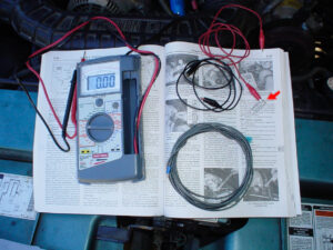
- Voltmeter. This must be high impedance to keep the meter itself from changing the sensors’ output. Digital Voltmeters will almost always be high impedance, but many analog voltmeters are low impedance and will invalidate the results. The one I show here is a useful design for automobile diagnosis because it also is low impedance, but also has an analog needle. This is especially useful in testing the Throttle Position (TP) Sensor
- Paper clip. (red arrow) This is used to backprobe the sensor terminals.
- Jumper wires with alligator clips
- Long wire for extending to vehicle interior (used for driving tests).
- Manual. The manual will tell you a lot. This document will help make sense of the manual.
Backprobing
Backprobing is a simple procedure that lets you test the voltage at a connector without removing the connector or modifying the wire. Ford was clever enough to build their wiring harness with these type of clips.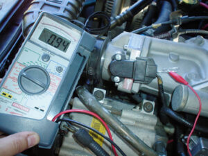
This image shows a paper clip inserted into the back of the TP sensor wiring clip. The alligator clip bridges the paper clip and the probe of the meter. I have used the meter’s probe itself, but it is bigger than the paperclip and could possibly damage the wiring clip. Also, the paper clip is less likely to fall out when doing a driving test because it is lighter.
Metering while Driving
Sometimes, you need to meter a sensor while you are operating the vehicle. This section shows how I run a wire to the passenger compartment in order to monitor the voltage from inside the vehicle.
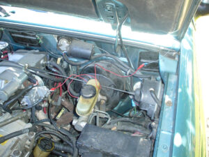
Note in this photo that there is a gray wire near the hood hinge. This wire can be routed temporarily into the passenger compartment by an open window or near the door hinge.
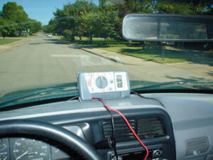
Once the wire is in the passenger compartment, put your meter on the dash or have a passenger hold it while the vehicle is in operation.
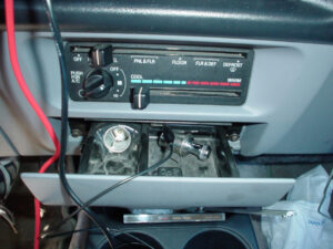
The ashtray compartment usually has a good ground source.
Throttle Position (TP) Sensor
The Throttle Position Sensor (TPS) lets the computer know how hard the driver is pressing the accelerator pedal. This is important because it lets the computer adjust for more assertive driving when needed, while maintaining optimal emissions/fuel economy under normal conditions.
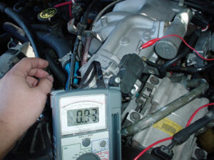
The TPS is a potentiometer (like a volume knob) that adjusts resistance based on the turning of the throttle plate. The most common problem with the TPS is a drop in the voltage somewhere in between idle and WOT. If there is a drop in voltage in the TPS, then the computer will think you are not pressing the pedal when you really are. Also, this will seem erratic, or will only happen at certain pedal positions.The TPS is tested with the key in the ON position but the engine not running. Backproble the signal wire on the wiring connector. There are 3 wires: one is the ground, one is the VREF (~5V), and the other is the signal. In this case, the top wire is signal.
At idle, the voltage should be just below 1V. Here it shows .93V, which is fine.
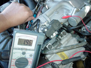
As you push the throttle cable mechanism, the voltage will slowly but gradually increase. This is where the needle comes in handy. If the needle drops at any point, then the TP sensor is exhibiting a “bad spot” and needs to be replaced.
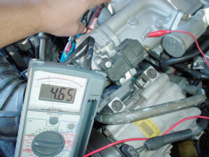
At Wide Open Throttle (WOT), the reading will be just under VREF (~5V). Here, the reading of 4.65V is fine.
Mass Air Flow (MAF) meter
This is a clever device that measures the amount of air passing into the engine. It has two wires, one which is heated, and one which is not. The unheated wire measures the air temperature. The heated wire is cooled by the incoming air, and the MAF calculates a voltage based on the amount of current required to keep the wire heated.
The MAF is very important to the proper operation of the vehicle. Since a proper ratio of air and fuel is required for good combustion, an error in this meter will cause the engine to run either rich or lean.
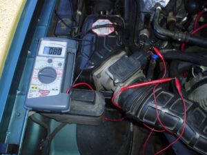
At idle, the MAF will read somewhere around 1V. The actual voltage will depend on the calibration of your vehicle, but the basic idea is that it will be low voltage at idle, and will increase with increased engine speed.
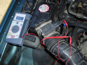
As you rev the engine, the voltage will increase. It is not a good idea to rev the engine excessively while not driving. This voltage of 1.78 is indicative of mid throttle.
I found it most useful to test this meter while driving. In particular, I noted how driving conditions affected the MAF voltage. At one time, my engine was bogging at WOT, and I found that the MAF showed about 3V at 75% throttle, but did not increase when I went to 100% throttle. Based on this, I purchased a larger MAF. This larger MAF reads all the way to WOT, up to 4.5V. Needless to say, the rich condition I having at WOT was corrected, and the bogging is no longer a problem.
